Using the application
This section details on how to use the application and its user interfaces.
S2E device discovery
S2E devices discovery on the network is performed by a UDP test server script (available at sw_serial_to_ethernet -> tests -> udp_test_server). This script needs to be executed on a host machine connected to a network router.
- Make sure the device is flashed with the firmware and web pages
- For Windows users, download Serial_to_Ethernet_UDP_test_server package (XM-004697-SM) and extract its contents to a directory. Navigate to (udp_test_server -> windows -> udp_server.exe), right-click on udp-server.exe and run as Administrator.
- For MAC or Linux users, it is recommended to install socket package for python, and run the script using the command python udp_server.py
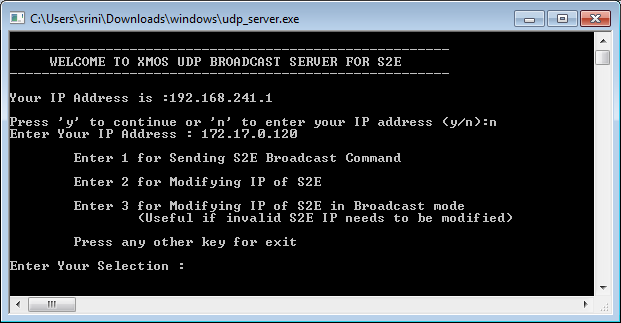
Running the UDP test server
- Select an appropriate host specific option as described above
- Script displays the selected network adapter on the console. If there are multiple network adapters on your host, ensure the ip address used by the script corresponds to the one used by your network adapter connected to the router
- Script displays different options to choose as explained in the following sections:
S2E device discovery using udp_test_server
Discover the S2E devices on the network
- Key in option 1 from the choices.
- Once the script is executed, it sends a broadcast request for all S2E devices in the network to respond. The message format is “XMOS S2E REPLY” broadcasted to 255.255.255.255
- XMOS S2E devices monitor this broadcast message and responds to the test server using the following format: “XMOS S2E VER:a.b.c;MAC:xx:xx:xx:xx:xx:xx;IP:abc.def.uvw.xyz”
- The test server parses this response received from S2E devices available in the network and displays the following information on the console: VER –> Firmware Version MAC –> MAC Address IP –> IP address of the S2E device
- The above information is displayed for all the S2E devices available in the network
Modify IP address of a particular S2E device
- Key in option 2 from the choices.
- The device discovery (option 1) should be used prior to using this option
- Upon selecting the above option, ensure all available S2Es on the network are displayed
- You can now select an appropriate S2E from the list and provide a new IP address for the selected S2E device. The server sends a unicast message using the format: “XMOS S2E IPCHANGE aaa.bbb.ccc.ddd”
- Appropriate S2E device will receive this message, flash the new ip address, resets and starts with the new ip address
- At the test server, you can now see S2E IP is changed to the new IP address by selecting the device discovery option again
Modify IP address of all S2E devices to use DHCP server
- Key in option 3 from the choices.
- This is a request and enables the s2e devices to DHCP mode. A DHCP server can be used to assign IP address to all S2E devices. The test server sends a broadcast message using the format: “XMOS S2E IPCHANGE 0.0.0.0”
- It is important that only the intended S2Es for which the IP address is invalid should be made available in the network All other S2Es should be removed from the network.
- Once the S2E devices IP is changed to the DHCP assigned IP addresses, select discovery option after some time in order to know the the new IP addresses for the device(s)
Data communication using S2E device
Apart from the standard UART and Telnet clients available on the host, following tools may be installed on the host system in order to use the S2E application.
- For Win 7 users, Hercules Utility by HW-Group available at http://www.hw-group.com/products/hercules/index_en.html
- For MAC users, SecureCRT7.0 utility available at http://www.vandyke.com/download/securecrt/
The following example uses Hercules 3.2.5
UART serial port setup
- Open the client application and change to Serial tab
- Select appropriate options in the Serial pane. Apply the default settings (Data size = 8, Parity = Even, Handshake = Off, Mode = Free) Cross check these settings with the UART settings in the webpage.
- Click Open
Telnet client setup
- Open the client application
- Switch to TCP Client tab
- Key in the ip address (for e.g. 169.254.196.178) of the s2e device
- Key in the port number configured for a particular UART (default configured values for each uart channel starts with 46)
- Click Connect
Telnet client connection to the s2e server is now opened; now key in the data to be sent to a particular UART. Files can also be uploaded using this client by right-clicking (and selecting appropriate option) in the data pane of either sessions.
Software is tested for the following telnet clients
- Putty
- Hercules
Device configuration using web interface
- Open the browser window
- Key in the ip address (for e.g. http://169.254.196.178/) of the S2E device and press Enter.
Home page of the application appears
- Click on a UART Channel to configure.
A new page for the selected channel appears with its settings. In order to change the UART parameters
- Select UART parameters to change (Parity, Stop bits, Baud rate, Char Len or Telnet port)
- Click Set.
- If configuration is set successfully, the Response text will say ‘Ok’
- Click on Back to main config page to select a different UART channel or save the current settings to flash.
- When clicked on Save in the main config page, current set configuration will be saved to flash. On successfull save, the Response text will say ‘Ok’
Software is tested for the following web browsers
- Google Chrome
- Mozilla Firefox
Device configuration using telnet interface
Telnet client can also be used for UART configuration or passing client data to UART channels (and vice versa). These are described as follows:
UART configuration
A separate telnet socket (default configured to port 23) is used for configuring UART channels via telnet client.
- Open the telnet client (following example uses Hercules 3.2.5)
- Switch to TCP Client tab
- Key in the ip address (for e.g. 169.254.196.178)
- Key in the port number (for UART config, it is 23)
- Click Connect
UART configuration server’s welcome message appears in the data pane of Telnet client
Use the following format for configuring an UART channel ~C~~P1~~P2~~P3~~P4~~P5~~P6~@
~ is the parameter separator
@ is command termination marker
- C : Command code
1 : Get channel configuration for a particular channel 2 : Set channel configuration 3 : Save current configuration of all channels to flash 4 : Restore and set channel configuration from flash
P1 : UART Channel Identifier (typical values range for 0 to 7)
- P2 : Parity Configuration (typical values range for 0 to 4)
0 : No Parity 1 : Odd Parity 2 : Even Parity 3 : Mark (always 1) parity bit 4 : Space (always 0) parity bit
- P3 : Stop bits configuration (typical values are 0 or 1)
0 : Single stop bit 1 : Two stop bits
- P4 : Baud rate configuration. Typical values (bits per second) include
115200 57600 38400 28800 19200 14400 9600 7200 4800 2400 1200 600 300 150
- P5 : UART character length. Typical values include
5 6 7 8 9
P6 : Telnet port (typical values are 10 to 65536)
- Click Enter to apply the configuration for the channel
Sample usage
- Get: ~1~~0~@
Gets channel ‘0’ configuration.
- Set: ~2~~0~~2~~0~~115200~~8~~100~@
Sets channel ‘0’ with: Even parity, single stop bits, 115200 baud, 8 character length and telnet port to communicate with this channel as 100.
- Save: ~3~@
Save current set configuration of all channels to flash
- Restore: ~4~@
Restores and sets channels configuration from flash