Overview
This document gives an overview of the XMOS modular development hardware platform. The system is based on a series of standard core boards which export the IO of one or more xcores, using two 36-pin card-edge PCI express connectors per core, into which add on boards (hereafter called slices) are plugged. The core boards can be chained together using some of these connectors where multi-core systems are required. Provision for attaching an XTAG2 debug adapter to the system of core boards is provided, along with power supplies, testpoints and so on.
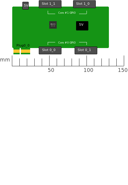
The two connectors (denoted 0 and 1) available to each xcore export the following capabilities:
| Resource | Conn. 0 | Conn. 1 |
|---|---|---|
| 1b ports | 4 | 12 |
| 8b ports | 2 | 2 |
| 5b xlinks | 2 | 0 |
| JTAG | yes | no |
Additionally, the core boards export connector 0 for xcore0 to a 36-pin PCI express compatible row of teeth.
What this means is that:
- An xcore can control two separate slices (one via connector 0 and one via connector 1) each having moderate IO requirements.
- An xcore can control a single slices each having a higher IO requirement using both 0 and 1 connectors.
- To link two core boards together, the connector 0 teeth can be plugged into the connector 0 slot on another baseboard, giving two 5b links between the two core boards along with the full complement of JTAG signals.