Ethercat Design Notes
The prototype environment to develop Ethercat is shown below. It comprises a single L2 motherboard, with 4 ethernet “slices”.The bottom left port is port 0, port 1, 2, and 3 are anticlockwise from there. The XN file included models that board with all four slices, but missing ports are automatically skipped.
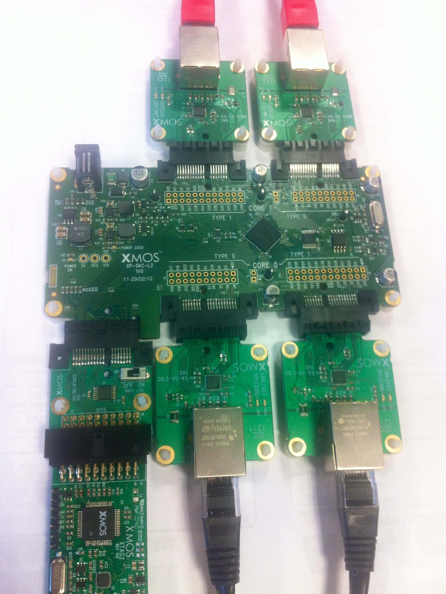
Photo of prototype ethercat system with 4 ports.
Introduction
Ethercat requires a short latency between incoming packet and outgoing packet. The key to meeting this latency is to use a different design method then usual for input and output.
Traditionally one would use 32 bit buffered ports to transport data. A port with this level of buffering creates a 31-bit latency between a bit arriving and a bit being processed; or 310 ns. Switching to 8 bit ports creates 70ns latency instead.
A second design criterion is that ports that are switched off should be bypassed. In our design we are achieving this by rerouting channel ends. The end of a channel always points to the first active transmit port. This method enables us to add no latency when skipping ports that are not in use.
An Ethercat system with N ports requires the following threads:
- Data Rx (N)
- Data Tx (N).
- Frame processing thread (1)
- Topology controller (1)
Data Rx and Tx
Each port has a data receive and transmit thread. The receive thread reads data of the MII port and outputs it over a streaming channel. The transmit thread reads data from a streaming channel and outputs this onto the MII ports. The protocol over the channel comprises unidirectional messages from Rx to Tx that are always delivered as a whole:
- A control token, either CT(3) that means original CRC attached or CT(0) that means no CRC in this stream, please compute one.
- A stream of data bytes comprising the Ethernet frame, including the CRC if it started with CT(3).
- A control token, either CT(0) that means original CRC was valid or CT(15) that means original CRC was not valid
- An END control token. This closes the channel, enabling it to be redirected if required.
The RX process will always set the destination of its output channel prior to transmitting a packet. That means that a whole packet is either transmitted to the current channel end, or a different one (if the topology changed). The RX process will always output a 3 token (CRC attached), and end with 0/15 as appropriate.
The TX process will store the start token, and compute a CRC on the data on the fly, but, if it gets to the final token it takes one of three decisions:
- The start token was CT(3): we have just outputted the original CRC, and hence we discard our CRC and stop transmitting; packet complete.
- The start token was CT(0) and the end token was CT(0): compute the final CRC, and transmit it.
- The start token was CT(0) and the end token was not CT(0): compute the final CRC, xor it with the final token (invalidating the CRC), and transmit the invalid CRC. This guarantees that an invalid CRC on input results in an invalid CRC on output.
Frame processing
Frame processing inputs and outputs the packet with the same channel protocol, but it replaces the initial ‘3’ control token with a ‘0’, and discards the last 4 btyes of the stream; discarding the CRC, and requesting the transmitter to compute a new one. This enables the frame processor to modify the data and implement mailboxes, reads, and writes.
Toplogy controller
The topology controller inspects, using SMI and INT_N wires, whether the PHYs are connected to other PHYs. Given the current configuration, it computes the first connected port for each port, and sets up the destination for each Rx process. Rx process 0 is always destined to the frame processor, but the FrameProcessor, Rx1, Rx2, and Rx3, communicate with whatever Tx is next. Fully populated they would transmit to Tx1, Tx2, Tx3, and Tx0; but if, say, nothing is plugged into port 2, then they would communicate with Tx1, Tx3, Null, and Tx0.
This is arranged through an array in some shared memory - the words contain destination addresses, are written byt he topology controller, and are read by the Rx/FrameController threads.