Analogue to Digital Converter (ADC) Interface
The analogue to digital interface currently provided is written for the 7265. This provides a clocked serial output following a sample and hold conversion trigger signal. The physical interface of the ADC is not covered in detail as the interface for ADC’s will vary from manufacturer to manufacturer. Examples of the interfaces for the MAX1379 and LTC1408 is also available in this module.
Besides the client and server interfaces the key issue discussed in this section is the synchronisation of the ADC to the PWM and how this is achieved on the ADC side.
The preprocessor define LOCK_ADC_TO_PWM must be 0 or 1 for off and on respectively. This defines whether the ADC readings are triggered by the PWM so that measurements can be taken at the appropriate point in the PWM cycle.
ADC Server Usage
The header file adc_7265.h and function call adc_7265_triggered are required to operate the ADC software as a server. This server is utilised in the case where the ADC is locked to the PWM.
See the API section for a full description of the function call.
ADC Client Usage
The functions below are the primary method of collecting ADC data from the ADC service.
The client can be utilised as follows:
#include "adc_client.h"

void do_adc_calibration(chanend c_adc);

{int, int, int} get_adc_vals_calibrated_int16(chanend c_adc);
do_adc_calibration(...) is used to initialise the ADC and calibrate the 0 point. The server will enter a mode where the next 512 samples are averaged, and the result is considered to be the zero point of further readings.
get_adc_vals_calibrated_int16(...) is used to get the three ADC values with the zero calibration, offset and scaling applied to get a signed 16 bit value. This is a multiple return function in channel order.
ADC Server Implementation
The ADC server implementation discussed here is the triggered variant of the ADC code. The ADC server first configures the ports as clocked inputs and outputs. Following this the main loop is entered.
ADC readings are triggered by the receipt of a trigger control token over the channel. A token is used as this offers minimum latency for channel communication. Following the token being received the ADC values are read after a time constant that is calibrated to align with the appropriate measurement point.
ADC values can be requested from the server at any point.
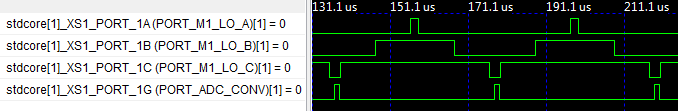
The screenshot shows three PWM ports and the ADC conversion trigger port. It shows that the ADC trigger rising edge, where the sample hold is made, is directly centred in the PWM channel inter-cycle period.