Programming Guide
This section discusses the programming aspects of the Multi-UART component and typical implementation and usage of the API.
Structure
This is an overview of the key header files that are required, as well as the thread structure and information regarding the buffering provision and requirements for the component.
Source Code
All of the files required for operation are located in the module_multi_uart directory. The files that are need to be included for use of this component in an application are:
| File | Description |
|---|---|
| multi_uart_rxtx.h | Header file for simplified launch of both the TX and RX server threads, also provides the headers for the individual RX and TX API interfaces. |
| multi_uart_common.h | Header file providing configuration ENUM definitions and other constants that may be required for operation |
| multi_uart_rx.h | Header file for accessing the API of the RX UART server - included by multi_uart_rxtx.h |
| multi_uart_tx.h | Header file for accessing the API of the TX UART server - included by multi_uart_rxtx.h |
Configuration of Multi-UART component
Multi-UART component configuration takes place in two domains - a static compile time configuration (discussed in this section) and a runtime dynamic configuration (as discussed in Initialisation and Reconfiguration of RX & TX Server.
Static configuration is done by the application providing configuration header files multi_uart_tx_conf.h and multi_uart_rx_conf.h.
Static configuration of UART TX
Below is a summary of the configuration options that are in the multi_uart_tx_conf.h file, their suggested defaults and an explanation of their function.
| Define | Default | Other options | Explanation |
|---|---|---|---|
| UART_TX_USE_EXTERNAL_CLOCK | (None) | Not defined | The presence of this define turns on or off the requirement to use external clocking this is discussed in Clocking. |
| UART_TX_CLOCK_RATE_HZ | 1843200 | 100000000 | Any valid clock rate | Defines the clock rate that the baud rates are derived from |
| UART_TX_MAX_BAUD_RATE | 115200 | less than or equal to 115200 | Define the max baud rate the API will allow configuration. Validated to 115200 |
| UART_TX_CLOCK_DIVIDER | (UART_TX_CLOCK_RATE_HZ / UART_TX_MAX_BAUD_RATE) | Any appropriate divider | It is recommended to leave this at the default. Is used to set the clock divider when configuring clocking from the internal reference clock |
| UART_TX_OVERSAMPLE | 2 | {1|2} | Define the oversampling of the clock - this is where the UART_TX_CLOCK_DIVIDER is > 255 (otherwise set to 1) - only used when using an internal clock reference |
| UART_TX_BUF_SIZE | 16 | {1,2,4,8,16,32,...} | Define the buffer size in UART word entries - needs to be a power of 2 (i.e. 1,2,4,8,16,32) |
| UART_TX_CHAN_COUNT | 8 | {1,2,4,8} | Define the number of channels that are to be supported, must fit in the port. Also, must be a power of 2 (i.e. 1,2,4,8) - not all channels have to be utilised |
| UART_TX_IFB | 0 | {0..n} | Define the number of interframe bits - n should not make the total number of bits in a UART word exceed 32 |
Static configuration of UART RX
Below is a summary of the configuration options that are in the multi_uart_rx_conf.h file, their suggested defaults and an explanation of their function.
| Define | Default | Other options | Explanation |
|---|---|---|---|
| UART_RX_CHAN_COUNT | 8 | {1,2,4,8} | Define the number of channels that are to be supported, must fit in the port. Also, must be a power of 2 (i.e. 1,2,4,8) - not all channels have to be utilised |
| UART_RX_CLOCK_RATE_HZ | 100000000 | System reference clock rate | Defines the clock rate that the baud rates are derived from |
| UART_RX_MAX_BAUD | 115200 | less than or equal to 115200 | Define the max baud rate the API will allow configuration. Validated to 115200. |
| UART_RX_CLOCK_DIVIDER | (UART_RX_CLOCK_RATE_HZ / UART_RX_MAX_BAUD) | Any appropriate divider | It is recommended to leave this at the default. Is used to set the clock divider when configuring clocking using either internal or external clocks. |
| UART_RX_OVERSAMPLE | 4 | Should remain at 4 | Oversample count for the max baud rate. It is recommended to leave this value as it is unless it is understood the effects that changing this value will have. |
Initialisation
The initialisation and configuration process for both the RX and TX operations is the same. For configuration the functions uart_rx_initialise_channel() or uart_tx_initialise_channel() is utilised. The flow is visualised in UART Initialisation Flow and a working example taken from the echo test application that is utilised for verification.
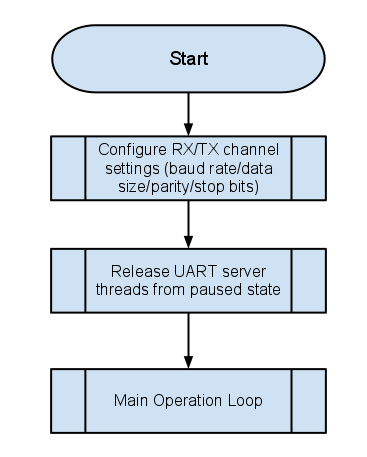
UART Initialisation Flow
The following working example is taken from echo_test.c and shows a typical initial configuration.
    /* configure UARTs */
    for (int i = 0; i < 8; i++)
    {
        if ((int)baud_rate <= 225)
            baud_rate = 225;

        if (uart_tx_initialise_channel( i, even, sb_1, start_0, baud_rate, 8 ))
        {
            printstr("Invalid baud rate for tx channel ");
            printintln(i);
        }

        if (uart_rx_initialise_channel( i, even, sb_1, start_0, baud_rate, 8 ))
        {
            printstr("Invalid baud rate for rx channel ");
            printintln(i);
        }

        printint(i); printstr(" => "); printint(baud_rate); printstr(" bps 8-E-1\n");
    }
The next stage of initialisation is to release the server threads from their paused state. Upon start up their default state is to be paused until the following channel communication is completed.
    /* release UART rx thread */
    do { temp = get_streaming_token(cRxBuf); } while (temp != MULTI_UART_GO);
    send_streaming_token(cRxBuf, 1);

    /* release UART tx thread */
    do { temp = get_streaming_token(cTxUART); } while (temp != MULTI_UART_GO);
    send_streaming_int(cTxUART, 1);
The above examples use the helper functions that are described in Multi-UART Helper API Multi-UART Helper API. However, if operating within the XC language normal channel interaction can be utilised such as the example below (from the simple test program).
    /* release UART rx thread */
    do { cUART :> go; } while (go != MULTI_UART_GO);
    cUART <: 1;
Interfacing to the TX Server
To transmit data using the TX server the application should make use of uart_tx_put_char(). An example use is shown below. This example, taken from the simple demo application configuration simply takes a string in the form of a character array and pushes it into the buffer one character at a time. When the API indicates that the buffer is full by returning a value of -1 then the loop moves onto the next channel.
       /* fill buffers with test strings */
       buffer_space = uart_tx_put_char(chan_id, 0xAA); //(unsigned int)test_str[chan_id][rd_ptr[chan_id]]);

       if (buffer_space != -1)
       {
           if (rd_ptr[chan_id] == 28)
               rd_ptr[chan_id] = 0;
           else
               rd_ptr[chan_id]++;
       }
       chan_id++;
       chan_id &= UART_TX_CHAN_COUNT-1;
This operation must be completed on the same core as the TX server thread as the communication module utilises shared memory.
Interfacing to the RX Server
To receive data from the RX server the application should make use of the channel that is provided. The channel provides notification to the application of which UART channel has data ready. The data itself is stored in a single storage slot with no buffering. This means that if the application layer fails to meet the timing requirements (as discussed in Client Timing Client Timing Requirements) data may be lost and/or duplicated.
The echo test example implements an application level buffering for receiving data. This may or may not be required in a particular implementation - dependant on whether timing requirements can be met. The receive and processing loop is shown below.
    while (1)
    {
        chan_id = (unsigned)get_streaming_token(cRxUART);

        /* get character over channel */
        uart_char = (unsigned)uart_rx_grab_char(chan_id);

        temp = uart_char;

        /* process received value */
        if ((rv = uart_rx_validate_char( chan_id, &uart_char )) == 0)
        {
            if (rx_elements[chan_id] < ECHO_BUF_SIZE)
            {
                rx_buffer[chan_id][rx_wr_ptr[chan_id]] = uart_char;
                rx_wr_ptr[chan_id]++;
                if (rx_wr_ptr[chan_id] >= ECHO_BUF_SIZE)
                    rx_wr_ptr[chan_id] = 0;
                rx_elements[chan_id]++;

            } else printstr("RX Buf Full\n");
        }
        else { printstr("RX Validation fail\n\t0x"); printhex(temp);printstr("\n\t");printintln(rv); }
    }
Once the token is received over the channel informing the application of the UART channel which has data ready the application uses the uart_rx_grab_char() function to collect the data from the receive slot. This provides an unvalidated word. The application then utilises the uart_rx_validate_char() to ensure that the UART word fits the requirements of the configuration (parity, stop bits etc) and provides the data upon return in the uart_char variable. This data is then inserted into a buffer.
Reconfiguration of RX & TX Server
The method for reconfiguring the UART software is the same for both the RX and the TX servers. When the application requires a reconfiguration then a call to uart_tx_reconf_pause() or uart_rx_reconf_pause() needs to be made. When reconfiguring the RX side the server thread will pause immediately, however when pausing the TX side the server thread will pause the application thread to allow the buffers to empty in the TX thread.
Once the functions exit the server threads will be paused. Configuration is then done utilising the same methodology as initial configuration using a function such as the uart_tx_initialise_channel() or uart_rx_initialise_channel().
Following the reconfiguration the application must then call uart_tx_reconf_enable() and uart_rx_reconf_enable() to re-enable the TX and RX threads respectively.
The listing below gives an example of reconfiguration that is taken from the echo test demonstration and test application.
                    uart_tx_reconf_pause( cTxUART, t );
                    uart_rx_reconf_pause( cRxBuf );

                    /* configure UARTs */
                    for (int i = 0; i < 8; i++)
                    {
                        if ((int)baud_rate <= 225)
                            baud_rate = 115200;

                        if (uart_tx_initialise_channel( i, even, sb_1, baud_rate, 8 ))
                        {
                            printstr("Invalid baud rate for tx channel ");
                            printintln(i);
                        }

                        if (uart_rx_initialise_channel( i, even, sb_1, start_0, baud_rate, 8 ))
                        {
                            printstr("Invalid baud rate for rx channel ");
                            printintln(i);
                        }

                        printint(i); printstr(" => "); printint(baud_rate); printstr(" bps 8-E-1\n");
                    }

                    baud_rate /= 2;

                    uart_tx_reconf_enable( cTxUART );
                    uart_rx_reconf_enable( cRxBuf );